Thanks for that Andrew, that's really interesting. Do different nozzle profiles influence the exhaust acceleration?
They do, but first this is a CFD (computational fluid dynamics) model of the nozzle on the work prior to mine conducted by the now Dr Sarah Barley. The image credit is as follows:
Barley, S. 2006. Micro-Chemical Monopropellant Thruster. Final Report for contract 043022. Surrey Space Centre.

The image may have to come down, but the entire research is kind of in the public domain.
This model uses a nozzle half angle of 15°. Note that the flow velocity is transonic across the narrowest part of the throat. The colour chart on the left is in m/s if you cannot see the finer print.
The light blue that hugs the nozzle on the way out is what is called the boundary layer. For thrusters the size we are developing boundary layers become a significant problem. Basically you cannot have supersonic flow over a surface; the heterogeneous interface causes a boundary layer in the flow. This is where the flow is subsonic over the nozzle surface. This happens in ALL nozzles. The only reason it is a problem, is because at these sizes it narrows the effective nozzle, to put it into perspective the throat on these thrusters is half a millimetre across. On amateur pyro rockets this IS REALLY unheard of. For pyro stuff you do not need to worry about boundary layers.
You may also notice that the flow accelerates further, after it leaves the nozzle!. On the top right and bottom right you can see the cross section of what is a ring of flow that is accelerated even more as it expands after leaving the nozzle. This is a really interesting result, yeah! This brings me onto the really importance of the the nozzle.
I wont go over your head and put in a load of mathematics, but instead I'll explain the result. To have the most efficient nozzle, we look at what is called expansion. In the image above the flow is underexpanded; but that is because it is in vacuum and you can never fully expand a flow into low ambient pressure. Basically the most efficient nozzle expands the flow so that the exit pressure is EQUAL to the pressure of the atmosphere. It the exit pressure is lower than the local atmosphere, you have
overexpanded the flow and if the exit pressure is higher than the local atmosphere you have
underexpanded the flow. Both give rise to losses and thus inefficiency. In launch vehicle design the nozzle is engineered to be correctly expanded about 2 3
rds of the way up for that stage.
If you have ever seen a launch, you would have noticed that the exhaust at sea level gets compressed even before leaving the nozzle and forms visible cones (these are shock waves). The flow is overexpanded and the higher atmospheric pressure compresses the flow. This is an image of a shuttle engine test at sea level.

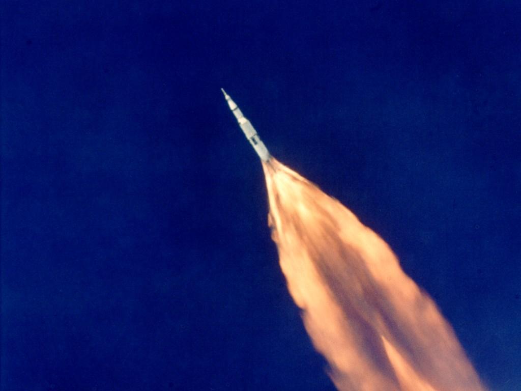
You would have also noticed that high up (lower atmospheric pressure), the exhaust plumes out sideways upon leaving the nozzle Below is a Saturn rocket being tested. It's the best image of underexpanded flow that I could find. I know that there are some fantastic ones but google is crap!!!

For us amateurs making rocket at will only ever experience sea level pressure we should design our nozzles accordingly. For this you need to be slightly mathematically minded to do the calculations, I can post the necessary formulae if you like. The half angle and geometry (profile) play an important role as well. For most of our applications a 15°-25° half angle and a straight cone are acceptable. The half angle you select really depends on what exit velocity you expect at that point, a faster exhaust flow needs to be expanded slower (smaller half angle). That is why the big nozzles are sort of bell shaped (approximately parabolic in profile); the slower flow just downstream of the throat is expanded faster and as it accelerates the flow is expanded slower (the half angle gets smaller). It'll be pretty difficult to tailor nozzle geometry for a small BP rocket, so for BP stick with 20°ish and just calculate the exit area and appropriate throat diameter, for higher I
sp propellants use a lower half angle 15°ish.
Edited by Andrew, 20 August 2007 - 10:26 AM.


