Jump to content


Photo

simple ? led circuit to confirm when a capacitor is charged


  • Please log in to reply
22 replies to this topic

#1 dave

dave

    Pyro Forum Regular

  • UKPS Members
  • 482 posts

Posted 02 September 2014 - 05:26 PM

is there a simple circuit I could use to light an led when a capacitor is charged ?
 
i'm charging a 50v 1000uf to 35 volts using a
XL6009 DC-DC Voltage Step Up Boost Converter (replace LM2577) 3-32v input.


just wanted a visual indication when the cap is charged.


if I connect the led with appropriate resistor across the cap surely It will be alight all the while the cap is charging ?


a quick sketch of a circuit would help if someone is familiar with electronics


#2 Arthur Brown

Arthur Brown

    General member

  • UKPS Members
  • 2,923 posts

Posted 02 September 2014 - 06:26 PM

A simple LED with resistor will start to glow at 5v and glow brighter all the way to 35v. I think you need a op amp or comparator so that the LED lights when a say 10% division of the cap volts reaches a preset volts. Circuit run off the battery volts.


Alternatively simply use 4 PP3 batteries in series or 3 small sealed lead batteries or a stack of AA cells


http://www.movember.com/uk/home/

Keep mannequins and watermelons away from fireworks..they always get hurt..

#3 Crazy Cat

Crazy Cat

    Member

  • General Public Members
  • PipPip
  • 83 posts

Posted 03 September 2014 - 03:48 AM

is there a simple circuit I could use to light an led when a capacitor is charged ?
 
i'm charging a 50v 1000uf to 35 volts using a
XL6009 DC-DC Voltage Step Up Boost Converter (replace LM2577) 3-32v input.
 
just wanted a visual indication when the cap is charged.
 
if I connect the led with appropriate resistor across the cap surely It will be alight all the while the cap is charging ?
 
a quick sketch of a circuit would help if someone is familiar with electronics

Capacitance Meter and RC Time Constants. http://arduino.cc/en...apacitanceMeter
http://www.learninga...to-light-an-led
http://www.learninga...-calculator.php
chargeCapacitortolightLEDschematic.jpg
The 9V power supply is changed to the 35V power supply, and placing a diode that will allow current to flow only when the voltage is 35 volts across the Capacitor to the LED when the power supply is turned off.
 
Charging photo flash capacitor.
zturbo2020.jpg
Using an old camera flash with LED capacitor indicator. http://desmond-downs...urbo-flash.html

http://easy-electron...r-remotely.html
hv+photo+flash+cap+charger+indicator+by+

To generate a flash, a Xenon flash bulb requires a special capacitor charged to a high voltage. This thesis will study methods to charge this photoflash capacitor from a low input voltage with a power limit. http://dspace.mit.ed...84/57146201.pdf

Capacitor charge indicator circuit. http://patentimages....US3649913-1.png
 

Two things are infinite: the universe and human stupidity; and I'm not sure about the universe. ― Albert Einstein ― Insanity is doing the same thing, over and over again, but expecting different results.


Explosives-Danger-Sign-S-1812.gif


#4 dave

dave

    Pyro Forum Regular

  • UKPS Members
  • 482 posts

Posted 03 September 2014 - 09:59 AM

just 2 question,
 
with the 9v circuit shown above (I will change to 35v, and a 2k resistor),
 
1)when the switched is pressed it will light the led showing charging not when the cap reaches 35v ? or does it gradually get brighter when nearing full charge


2)when the switch is released, will not the led then drain the capacitor and fade out when discharged ?


thanks for the above and the links, some of which I had checked out


#5 whoof

whoof

    Pyro Forum Regular

  • General Public Members
  • PipPipPip
  • 399 posts

Posted 03 September 2014 - 03:36 PM

Led in series with resistor and say 30 v zener diode ?

#6 Crazy Cat

Crazy Cat

    Member

  • General Public Members
  • PipPip
  • 83 posts

Posted 04 September 2014 - 01:27 AM

just 2 question,
 
with the 9v circuit shown above (I will change to 35v, and a 2k resistor),
 
1)when the switched is pressed it will light the led showing charging not when the cap reaches 35v ? or does it gradually get brighter when nearing full charge
 
2)when the switch is released, will not the led then drain the capacitor and fade out when discharged ?

I'll re-draw the circuit diagram later tomorrow if I have time, and include an explanation that also answers your 2 questions. Best I can do with my busy administration responsibilities.
 

Two things are infinite: the universe and human stupidity; and I'm not sure about the universe. ― Albert Einstein ― Insanity is doing the same thing, over and over again, but expecting different results.


Explosives-Danger-Sign-S-1812.gif


#7 megabusa

megabusa

    Pyro Forum Regular

  • General Public Members
  • PipPipPip
  • 280 posts

Posted 04 September 2014 - 07:53 AM

Yes - the LED will discharge the cap.


Why do you need a LED ? You can work out the time constant to charge the cap quite easily.


I suspect, how you are charging it, from a supply, the time constant will be very low due to low output impedance of the supply. This will mean the charge time is negligible for a 1000 uF cap.


In the diagram above (with the 9v battery) the LED will be very bright (possibly even burn out) at 35v with a 470R resistor in there & it would discharge the cap in a few hundred mSec.


At 35v, I would use something like a 3k3 resistor. This would give around 10mA through the LED, which personally, I find bright enough without over-driving the LED. Even so, when the supply is removed the cap would discharge in about 3 sec.


The problem with an LED is it takes around 10 - 20mA (give or take depending on type) to power it, so unless you are leaving the supply on to keep the cap charged the LED will drain the cap quickly.


I'm not sure what you are trying to build, so apologies for the vague answers.


Cheers,


Phil.


#8 Arthur Brown

Arthur Brown

    General member

  • UKPS Members
  • 2,923 posts

Posted 04 September 2014 - 08:06 AM

Many ordinary leds will work from 2mA to 20mA that's limited by the resistor, daytime outdoors or in comfortably lit rooms 10+ma may be needed but in the dark outdoors or in the wings of a theatre 2 - 5mA is fine.


It's quite normal to eat up a big battery full of electricity running a panel of LEDs and use very little for actually firing igs. 


http://www.movember.com/uk/home/

Keep mannequins and watermelons away from fireworks..they always get hurt..

#9 dave

dave

    Pyro Forum Regular

  • UKPS Members
  • 482 posts

Posted 04 September 2014 - 07:30 PM

megabusa,


an led is just a nice indicator to visually see


its actually for trying to build a small spot welder to try and weld 41awg nichrome wire to copper wire.

but I'm not having much success, the nichrome wire is usually destroyed and not welded.


a bit like the welders for this new e cigarette stuff that seems to have taken off, rightly or wrongly.


thanks to all for continuing replies


#10 Crazy Cat

Crazy Cat

    Member

  • General Public Members
  • PipPip
  • 83 posts

Posted 05 September 2014 - 08:32 AM

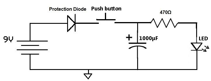
With the 9v circuit shown above (I will change to 35v, and a 2k resistor),

(1) when the switched is pressed it will light the led showing charging not when the cap reaches 35v ? or does it gradually get brighter when nearing full charge.

When the 9V power supply charges the 1000 uF capacitor, it will also cause the LED to glow. When the 9V power supply is disconnected the

(2) when the switch is released, will not the led then drain the capacitor and fade out when discharged ?

When the 9V power supply is disconnected, the 1000 uF capacitor will act as the power supply and discharge. Most LED's work at a 2-3 volt range.
 
Now look at schematic 1.jpg diagram.

There you'll see the original 9V circuit re-draw, with the Zener diode (IN4728, 3.3V) and the push button switch.

(1) When the 9V power supply is connected, it will charge the 1000 uF capacitor.
(2) When the 9V power supply is disconnected, the 1000 uF capacitor will act as the power supply, and if you press the push button switch, it will cause the LED to glow, because the Zener diode is rated at 3.3V and it allows current to flow when The voltage is higher than 3.3V.
(3) When the push button switch is released, the 1000 uF capacitor is isolated and therefore won't discharge.

Voltages measured between 1 & 2 = 2.32V and 2 & 3 = 5.53V

 
Now, for the 35V circuit.

R = (35/9) x 470 = 1827.8 ohms.

Zener diodes.
IN4751 = 30V
IN4752 = 33V
IN4753 = 35V <=???
IN4761 = 75V

If you need the 1000 uF capacitor within a voltage range of say, 30V - 33V

Red LED with IN4751 = 30V
Green LED with IN4752 = 33V

Finally, look at schematic 2.jpg diagram. An alternative?
schematic 1.jpg schematic 2.jpg

Edited by Crazy Cat, 05 September 2014 - 08:35 AM.


Two things are infinite: the universe and human stupidity; and I'm not sure about the universe. ― Albert Einstein ― Insanity is doing the same thing, over and over again, but expecting different results.


Explosives-Danger-Sign-S-1812.gif


#11 dave

dave

    Pyro Forum Regular

  • UKPS Members
  • 482 posts

Posted 05 September 2014 - 10:17 AM

thank you for that cat,


I think I will go with the 2nd jpg, and adjust components for 35v


charging = red

fully charged = not red


many thanks again for your help


#12 Crazy Cat

Crazy Cat

    Member

  • General Public Members
  • PipPip
  • 83 posts

Posted 05 September 2014 - 11:39 PM

thank you for that cat,

I think I will go with the 2nd jpg, and adjust components for 35v

charging = red
fully charged = not red

many thanks again for your help

Your welcomed Dave.

Just a note with the schematic 2.jpg diagram. C1 and R1 act as the RC Time Constants circuit, and you can use Capacitor Charge (Charging) Calculator. http://www.learninga...-calculator.php
If R1 is low, or very low ohms, the C1 will charge quickly.
RCSchem.png

Something else that will interest you, Spot Welder construction.

http://www.diyotron....pot_Welder.html
http://www.pittnerov...tronics/welder/
http://www.turtlesar.../cd_welder.html

Edited by Crazy Cat, 05 September 2014 - 11:54 PM.


Two things are infinite: the universe and human stupidity; and I'm not sure about the universe. ― Albert Einstein ― Insanity is doing the same thing, over and over again, but expecting different results.


Explosives-Danger-Sign-S-1812.gif


#13 whoof

whoof

    Pyro Forum Regular

  • General Public Members
  • PipPipPip
  • 399 posts

Posted 06 September 2014 - 03:42 PM

megabusa,

an led is just a nice indicator to visually see

its actually for trying to build a small spot welder to try and weld 41awg nichrome wire to copper wire.
but I'm not having much success, the nichrome wire is usually destroyed and not welded.

a bit like the welders for this new e cigarette stuff that seems to have taken off, rightly or wrongly.

thanks to all for continuing replies

With dissimilar wire sizes normal practice is to fold the thicker wire over and weld to itself.
Like in the old incandescent bulbs although i think they were cold welds.
You have different metals with vastly different melting points.

Also you should not pass current through the thinner wire just the thicker one.
Using a higher clamping pressure with current delivered through the clamping faces not the wire may help.

Edited by whoof, 06 September 2014 - 04:04 PM.


#14 whoof

whoof

    Pyro Forum Regular

  • General Public Members
  • PipPipPip
  • 399 posts

Posted 06 September 2014 - 04:13 PM

Fwiw i dont bother with nichrome any more.

Stripping a section of stranded wire and pulling sleves each side gives a gap in the middle.
Fold over and cut the strands leaving one.
No soldering required.
Good enough for my experiments.

Edit.
Fine wire welders are normally pulse controlled but you may improve things by paralleling up capacitors and charging to a lower voltage.
35 v is a bit high for what you are trying to do.

Heres a picture.
http://www.weldingne.../cross-wire.pdf

Edited by whoof, 06 September 2014 - 06:21 PM.


#15 dave

dave

    Pyro Forum Regular

  • UKPS Members
  • 482 posts

Posted 07 September 2014 - 11:14 AM

thanks for the additional info woof


I think you are correct re the "welding pressure" and pulse control would be better


as you know commercial units are expensive and for what I want cant be justified


1 user(s) are reading this topic

0 members, 1 guests, 0 anonymous users